
 9 minutes
Content
In recent years, the global community has been facing a rapidly growing challenge in waste management and energy supply. With the rise of industrialization, urbanization, and consumerism, the world is producing an enormous volume of waste—ranging from used tires and plastics to municipal solid waste and biomass residues. Conventional disposal methods such as landfilling and incineration not only occupy vast areas of land but also cause severe secondary pollution, releasing greenhouse gases and toxic emissions into the environment. Against this backdrop, pyrolysis technology has emerged as a revolutionary solution that converts waste materials into valuable energy resources through a clean and efficient thermal process.
Pyrolysis is a thermochemical decomposition process that breaks down organic materials under high temperature in the absence of oxygen. Unlike combustion, which involves complete oxidation and releases large quantities of CO₂ and heat, pyrolysis transforms complex hydrocarbons into simpler molecules, producing pyrolysis oil, combustible gas, and carbon black. These outputs can be reused as industrial fuels, chemical feedstocks, or even in material reinforcement applications, making pyrolysis a crucial pillar of the modern circular economy.
However, traditional pyrolysis systems, often referred to as batch-type reactors, have limitations. They operate on a stop-and-go cycle—loading waste, heating, cooling, and discharging residue before restarting the process. This intermittent operation results in lower efficiency, inconsistent product quality, and higher energy consumption. To address these challenges, engineers and environmental technologists have developed Continuous Pyrolysis Machine, a breakthrough innovation that allows uninterrupted waste feeding and product discharge, achieving continuous and stable production.
Continuous pyrolysis represents the next stage in the evolution of thermal decomposition technology. In this system, waste materials are automatically fed into a sealed reactor that operates at a constant high temperature, typically between 350°C and 600°C, depending on the feedstock type. Inside the reactor, the waste undergoes continuous heating and decomposition, and the resulting vapors and gases are continuously extracted, condensed, and separated into various products. The solid residues—mainly carbon black or char—are discharged through an automated cooling system, maintaining safe and stable operation.
This uninterrupted operation not only improves energy efficiency but also significantly enhances production capacity and consistency. Continuous pyrolysis systems can operate 24 hours a day with minimal manual intervention, thanks to advanced automation and temperature control mechanisms. They are particularly suitable for large-scale industrial applications such as waste tire recycling plants, plastic-to-fuel facilities, and oil sludge treatment lines.
The importance of continuous pyrolysis technology extends beyond industrial productivity. It is fundamentally linked to global sustainability goals and environmental preservation. Every year, approximately 1.5 billion waste tires and 300 million tons of plastic waste are generated worldwide. A large portion of these materials ends up in landfills or the natural environment, taking hundreds of years to decompose. By converting these non-biodegradable wastes into reusable energy, continuous pyrolysis equipment provides a sustainable pathway to reduce pollution, recover resources, and cut carbon emissions.
Furthermore, the outputs of the pyrolysis process are highly versatile:
Through these outputs, continuous pyrolysis transforms environmental liabilities into valuable assets. It not only diverts waste from landfills but also helps industries achieve energy independence and resource efficiency.
The growing emphasis on renewable energy and carbon neutrality has pushed governments and industries to explore cleaner production technologies. Continuous pyrolysis stands out because it bridges the gap between waste treatment and energy generation. Unlike recycling, which often depends on clean and sorted materials, pyrolysis can handle mixed and contaminated waste streams, offering a robust alternative for complex waste types that are difficult to recycle mechanically.
From an energy perspective, pyrolysis-derived fuels can supplement or even replace fossil fuels in certain sectors. For instance, pyrolysis oil can power boilers, furnaces, and generators, while the recovered gas can sustain the system’s heating requirements, drastically reducing external energy input. This self-sustaining mechanism makes continuous pyrolysis equipment an ideal candidate for integrated waste-to-energy plants, especially in regions where energy infrastructure and waste management systems are underdeveloped.
Technological advancements have made modern continuous pyrolysis systems more automated, efficient, and environmentally friendly than ever before. Features such as real-time monitoring, intelligent temperature control, automated feeding and discharging systems, and advanced gas cleaning units allow for safer and more stable operations. These improvements also lead to higher oil yield rates, lower maintenance costs, and reduced emissions, making the system attractive from both environmental and economic standpoints.
Economically, continuous pyrolysis plants offer a viable return on investment by generating multiple revenue streams: the sale of pyrolysis oil, the reuse of carbon black, and the potential carbon credit benefits. Many enterprises also gain additional advantages through reduced waste disposal fees and compliance with environmental regulations.
As the world transitions toward sustainable development and circular economy models, continuous pyrolysis equipment plays an increasingly central role. It exemplifies how modern engineering can convert waste into wealth while aligning with environmental goals. Whether deployed in tire recycling, plastic recovery, or biomass conversion, this technology symbolizes a future where waste is no longer a burden, but a renewable resource.
In essence, continuous pyrolysis technology embodies a transformative approach—closing the loop between waste generation and energy production. It delivers not only tangible economic benefits but also contributes to global efforts in mitigating pollution, conserving resources, and achieving carbon neutrality. With continuous innovation and wider industrial adoption, pyrolysis is poised to become one of the defining technologies in the next generation of sustainable manufacturing and energy systems.
Continuous pyrolysis equipment operates on a seamless and automated system that thermally decomposes waste materials into valuable by-products—oil, gas, and carbon black—without direct contact with oxygen. Unlike batch systems that process material in cycles, continuous pyrolysis achieves uninterrupted feed-in, reaction, and discharge, allowing round-the-clock production.
The following points describe the core working principles and key stages of the process.
Temperature Range:
Inside the main reactor, the temperature typically ranges from 350°C to 600°C, depending on the type of feedstock. Plastics generally require higher temperatures than rubber or biomass.
Anaerobic Environment:
The absence of oxygen ensures that the material does not burn but instead decomposes into smaller hydrocarbon molecules.
Thermochemical Reaction:
Under high heat, long-chain organic polymers break down into:
Continuous Heating Source:
The system is typically heated by burners using fuel oil, natural gas, or the non-condensable gas produced by the pyrolysis itself—making the system partly self-sufficient in energy.
Vapor Collection:
The hot vapor mixture exiting the reactor contains hydrocarbons in both gaseous and vaporized liquid form. These vapors are directed into a condensation system.
Condensation Units:
The system typically includes multiple condensers or heat exchangers, which cool the vapors down to form liquid oil.
Oil Storage:
The condensed liquid is collected in storage tanks as pyrolysis oil, which can be used directly as fuel or refined into diesel or other chemicals.
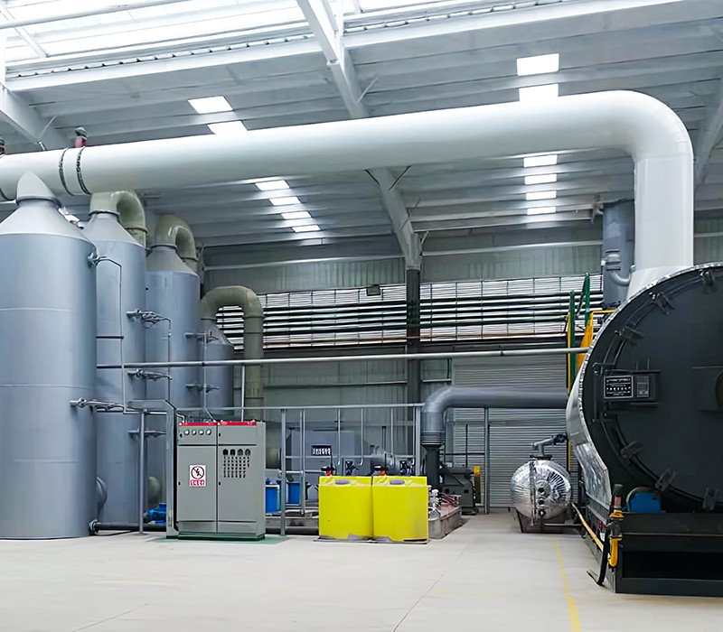
Exhaust Treatment System:
The hot exhaust gas generated by burners or reactor heating passes through a series of cleaning stages, including:
Emission Compliance:
With proper treatment, the exhaust gas can meet strict environmental standards (e.g., EU or EPA regulations). This ensures the entire process remains eco-friendly and pollution-free.
Heat Recovery Options:
Some systems reuse waste heat from flue gases for feedstock drying or pre-heating, further enhancing energy efficiency.
Input:
Waste feedstock (plastic, rubber, biomass) + auxiliary heating source (or recycled gas)
Process:
Pyrolysis reaction → Vapor condensation → Gas recycling → Carbon discharge
Output:
This closed-loop system minimizes energy loss and maximizes product recovery, achieving both economic efficiency and environmental compliance.
The working principle of continuous pyrolysis equipment demonstrates the perfect synergy between thermal science, automation technology, and environmental engineering. By maintaining an oxygen-free continuous process, this system transforms various waste streams into valuable fuel and material resources. Its high efficiency, safety, and scalability make it a core technology for the modern waste-to-energy industry. Understanding each operational stage—feeding, heating, reaction, condensation, and discharge—reveals why continuous pyrolysis stands at the forefront of sustainable waste management solutions.
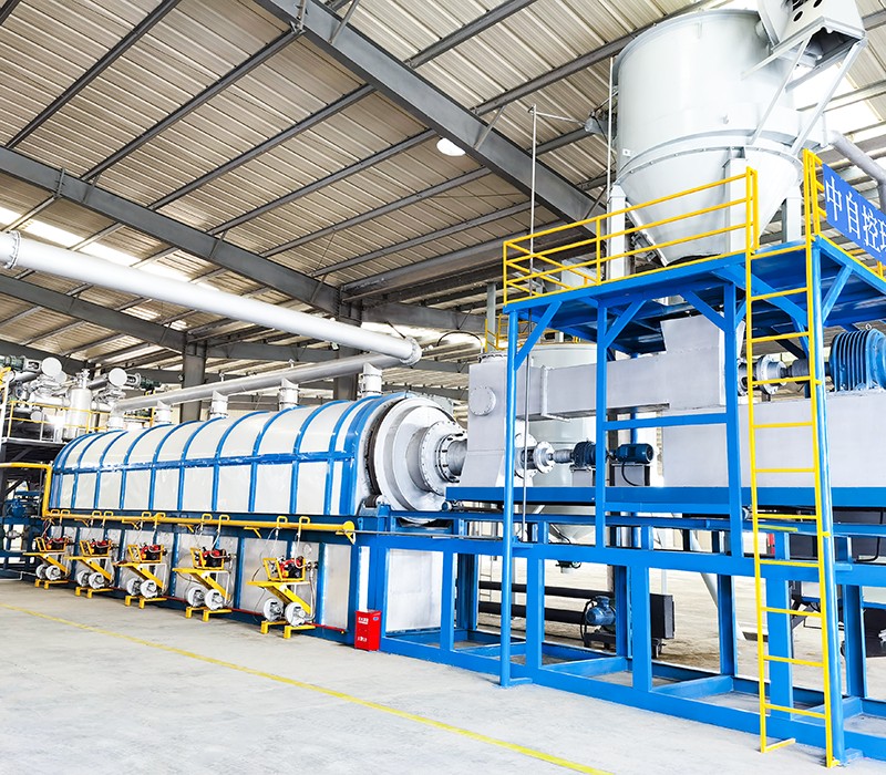
A continuous pyrolysis system is an integrated assembly of high-precision machinery designed to convert waste materials into usable products efficiently, safely, and continuously.
To achieve reliable 24-hour operation, every subsystem must work in harmony — from waste feeding and thermal decomposition to oil condensation, gas recovery, and emission control.
Below is a detailed overview of the main components that make up a modern continuous pyrolysis plant.
The feeding system serves as the entry point of the entire process, ensuring a stable and continuous flow of raw material into the pyrolysis reactor.
Key Benefits:
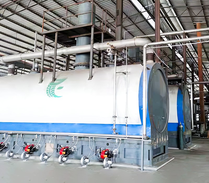
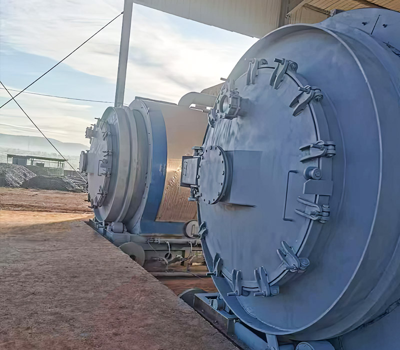
The reactor is the heart of the pyrolysis system — where the actual thermal decomposition occurs.
Design Types:
Construction Materials:
Typically made of high-grade alloy steel or refractory-lined carbon steel to withstand extreme temperatures and corrosion from volatile hydrocarbons.
Heating System:
The reactor is heated externally by burners using either fuel oil, natural gas, or the system’s own recycled gas. The temperature is controlled in multiple zones for precision.
Working Temperature:
Generally between 350°C and 600°C, depending on feedstock characteristics.
Residence Time:
30–90 minutes for full decomposition, ensuring maximum oil recovery and minimal char formation.
Internal Mixing:
Some designs include spiral paddles or slow rotation to ensure even contact between material and heat.
Key Benefits:
After pyrolysis, hot hydrocarbon vapors are directed into a condensation system where they are cooled and converted into liquid oil.
Key Benefits:
Not all gases can be condensed into liquid form — the remaining non-condensable gas (NCG) is rich in light hydrocarbons such as methane, ethane, and hydrogen.
Instead of releasing it, the system reuses this gas as an internal energy source.
Key Benefits:
After the thermal decomposition is complete, the remaining solid residue — primarily carbon black, metal (if tires are used), and ash — must be continuously removed.
Key Benefits:
Environmental protection is a crucial aspect of modern pyrolysis operations. Advanced purification systems ensure all emissions comply with international standards.
Key Benefits:
Automation and precision control are key to the performance and safety of continuous pyrolysis systems.
Key Benefits:
Several auxiliary units enhance the reliability, efficiency, and convenience of the pyrolysis operation.
Key Benefits:
Each component in continuous pyrolysis equipment plays a distinct but interdependent role in achieving efficient, safe, and eco-friendly operation.
From automatic feeding to intelligent control systems, every subsystem contributes to maximizing yield, minimizing emissions, and ensuring 24/7 stable production.
The integration of these components transforms waste materials — such as plastics, rubber, or biomass — into valuable energy and industrial resources, setting a new benchmark for sustainable waste management and renewable energy generation.


Let's Pyrolysis!


 +44 7529 150720
  [email protected]
  300 meters east of the South Railway Station in Shangqiu City, Henan Province
  Global Waste-to-Energy Solutions Waste Resource Utilization Equipment Manufacturer
 English
 русский
 Français
 Español
 عربى
عربى